PLC devices
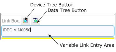
You can specify PLC devices in the Variable Link entry area.
To pass data from PLC devices, specify the PLC devices in this area.
There are two methods to specify PLC devices.
1. Click the Device Tree button and select the devices on the Device Tree.
The devices that are displayed in the Device Tree are the devices that are used in WindLDR.
2. Directly enter devices in the Variable Link entry area. Refer to the following for the input format.
■ Device format
1. Bit device
The format to specify a bit device is as follows.
Format: "IDEC" ":" "Symbol" ":" "Address"
Example: To specify internal relay M0050 IDEC:M:M0050
2. Word device
The format to specify a word device is as follows.
When you specify a bit in a data register, specify the bit address after the data type “Bit”.
Format: "IDEC" ":" "Symbol" ":" "Address" "." "Data type"
Example: To specify data register D0050 as data type Word IDEC:D:D0050.Word
Example: To specify the 15th bit in the data register D0050 as data type Bit, IDEC:D:D0050.Bit15
| Device | Symbol | Unit | Data Type (Word device) | 16-I/O Type | 24-I/O Type | 40-I/O Type |
|---|---|---|---|---|---|---|
| Input | I | Bit | - | I0 to I10/I30 to I507 | I0 to I15/I30 to I627 | I0 to I27/I30 to I627 |
| Output | Q | Bit | - | Q0 to Q6/Q30 to Q507 | Q0 to Q11/Q30 to Q627 | Q0 to Q17/Q30 to Q627 |
| Internal Relay | M | Bit | - | M0 to M7997/M10000 to M17497 | M0 to M7997/M10000 to M17497 | M0 to M7997/M10000 to M17497 |
| Special Internal Relay | M | Bit | - | M8000 to M8317 | M8000 to M8317 | M8000 to M8317 |
| Shift Register | R | Bit | - | R0 to R255 | R0 to R255 | R0 to R255 |
| Timer | T | Bit | - | T0 to T1023 | T0 to T1023 | T0 to T1023 |
| Timer Preset Value | TP | Word | Word | TP0 to TP1023 | TP0 to TP1023 | TP0 to TP1023 |
| Timer Current Value | TC | Word | Word | TC0 to TC1023 | TC0 to TC1023 | TC0 to TC1023 |
| Counter | C | Bit | - | C0 to C511 | C0 to C511 | C0 to C511 |
| Counter Preset Value | CP | Word | Word/Double | CP0 to CP511 | CP0 to CP511 | CP0 to CP511 |
| Counter Current Value | CC | Word | Word/Double | CC0 to CC511 | CC0 to CC511 | CC0 to CC511 |
| Data Register | D | Word | Word/Integer/Double/Long/Float | D0000 to D7999/D10000 to D55999 | D0000 to D7999/D10000 to D55999 | D0000 to D7999/D10000 to D55999 |
| Special Data Register | D | Word | Word/Integer/Double/Long/Float | D8000 to D8499 | D8000 to D8499 | D8000 to D8499 |
Linking to WindLDR
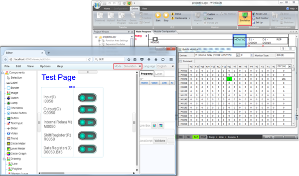
You can link the system to the WindLDR simulation function when you have specified PLC devices in the Variable Link area.
Link to the WindLDR simulation function with the following procedure.
1. Click Simulation on the WindLDR ribbon menu to start the simulation.
2. Set the Web Page Editor operation mode to run mode.
When data is input from a PLC device
You can check the operation of the system by changing device values in the WindLDR Batch Monitor dialog.
When data is output to a PLC device
You can check device values in the WindLDR Batch Monitor dialog.
When 32-bit data storage setting is changed on Function Area Settings dialog box, the changed setting is applied to the web page editor once a project is saved and opened.